


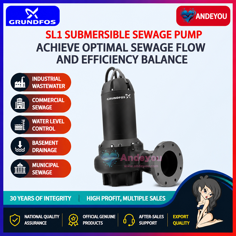
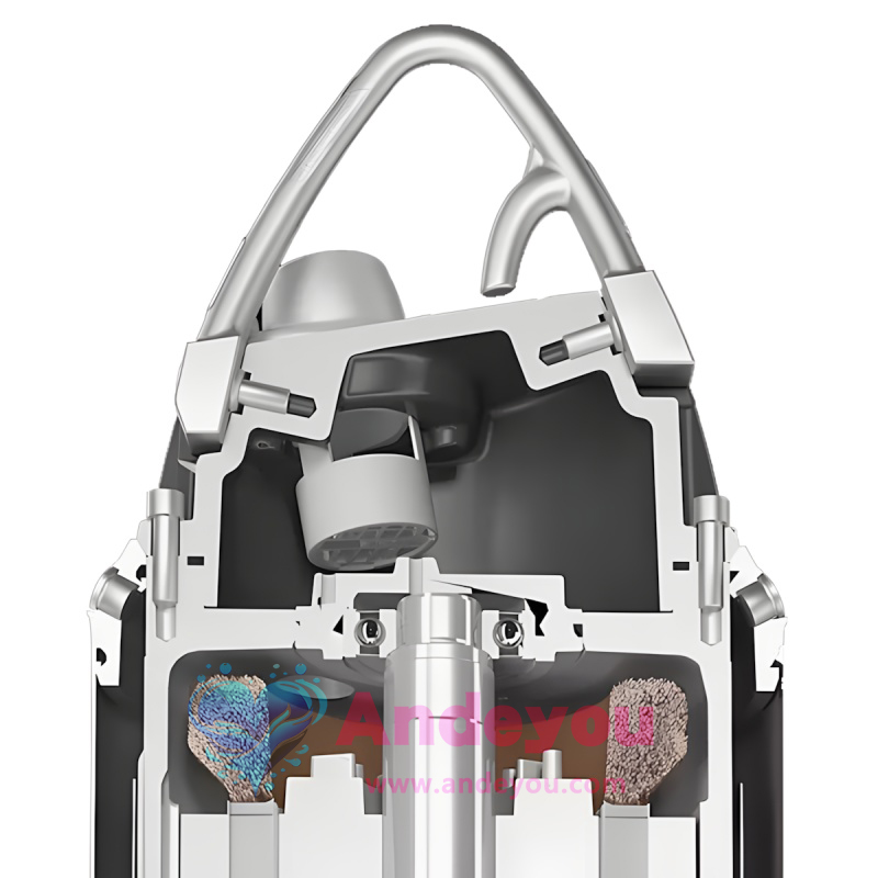
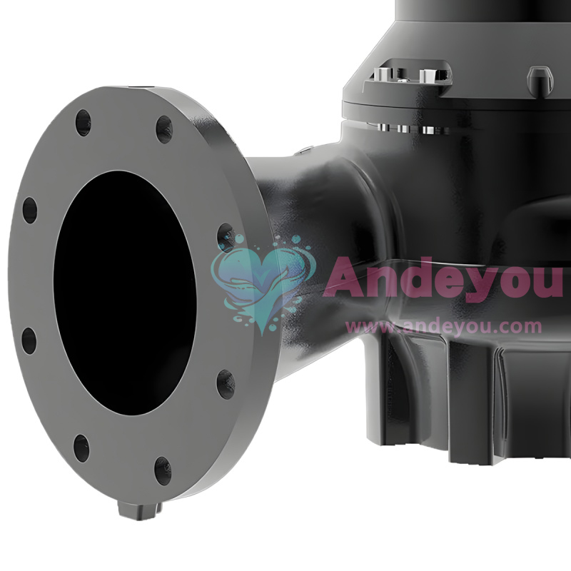
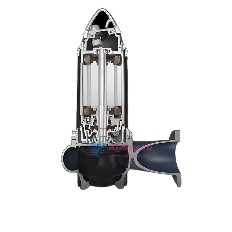
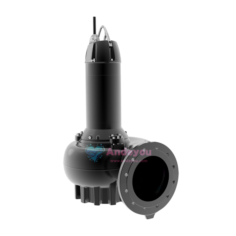
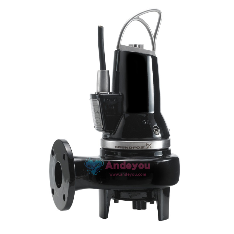
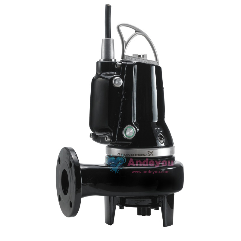
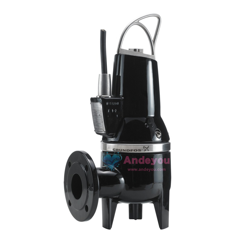
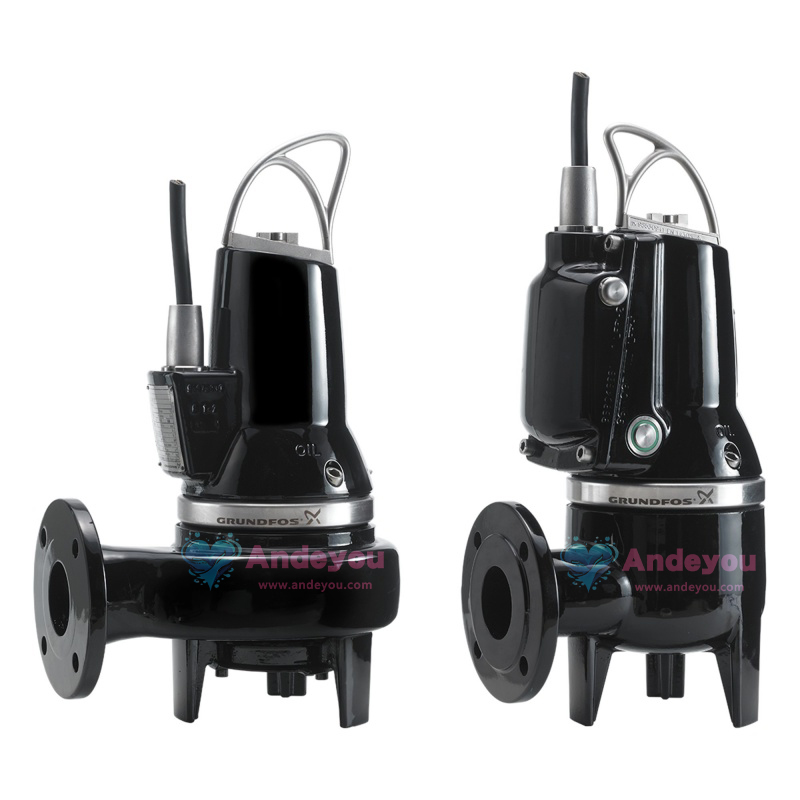
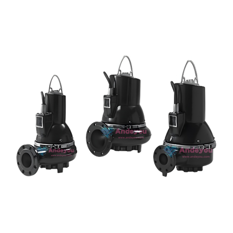
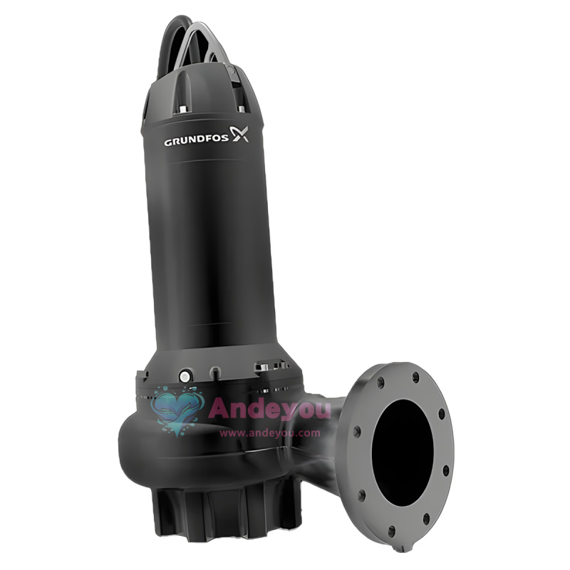
GRUNDFOS SE/SL1 Series Submersible Sewage Pumps (Suitable for Municipal and Industrial Applications)
I. Core Product Series
Model Classification
SE1.50: Power ≥ 2.2 kW
SE1.80/SE1.100: Large diameter design, supporting 80mm and 100mm particles respectively
SEV.65: Power ≥ 2.2 kW
SEV.80/SEV.100: SuperVortex impeller design, suitable for liquids containing fibers or viscous liquids
Electrical Parameters
Voltage: Three-phase 380-415V (supports DOL/Y-D start) or 220-240V
Frequency: 50Hz
Speed: Two-pole (3000 min⁻¹) or four-pole (1500 min⁻¹)
II. Explosion-proof Safety Features
Explosion-proof Certification
European Standard:
CE 0344 II 2 GD, EEx dc IIB T4/T3 (supports 200°C with inverter)
IP68 protection rating, fire-resistant housing (unauthorized intervention prohibited)
Australian Standard: Ex nA II T3 (compliant with IEC 79-15)
Maintenance Restrictions
Components permitted for unauthorized repair: pump casing, impeller, sealing rings, wear rings, shaft seal
Components requiring authorized service station operation: stator, rotor, and other core motor components
III. Structural and Performance Characteristics
Impeller Design
Channel impeller (Code 1): Suitable for large particle wastewater (e.g., SE1.80)
Vortex impeller (Code V): Non-clogging design, suitable for fibrous liquids
Materials and Sealing
Oil chamber uses Shell Ondina 917 lubricating oil (0.3-0.7L capacity)
Double shaft seal protection, oil chamber pressure relief design
O-rings use Rocol 22. Lubricant and sealing rings need to be replaced regularly.
Torque and Assembly
Standardize the torque of key screws (e.g., M8 screw 12±2 Nm, M10 screw 50±5 Nm). Nm)
Special tool support (e.g., stator guide, wear ring clamp)
IV. Intelligent and Safety Functions
Thermal Protection
Stator built-in thermal switch (150°C trigger shutdown), explosion-proof models require manual restart
Use with LC-Ex4 safety barrier (potentially explosive environments)
Monitoring and Maintenance
Recommended maintenance every 3000 hours or year
Inspection items: oil water content, cable integrity, impeller wear, bearing noise
V. Application Scenarios
Municipal Sewage: Suitable for drainage systems containing solid particles (≤100mm)
Industrial Wastewater: Treats oily, fibrous, or high-viscosity liquids (e.g., SEV series)
Hazardous Environments: Explosion-proof models can be used in areas with explosive gases such as petroleum and chemical plants
VI. Installation and Operation Points
Electrical Connections
Grounding wire cross-sectional area ≥4 mm² (yellow-green bicolor wire)
Requires matching motor protection circuit breaker (e.g., Grundfos CU100 controller)
Startup Verification
Confirm rotation direction by comparing flow rate or pressure (arrow direction marked on pump top cover)
Incorrect rotation direction will cause performance degradation; two phases of power supply need to be swapped.
VII. Troubleshooting (Partial Examples)
|
Symptom of the fault |
Possible causes |
Solution |
|
Motor fails to start |
Impeller blockage / Power supply short circuit |
Clean the impeller or check the cable. |
|
Thermal switch trips |
Liquid temperature is too high. |
Cool the liquid or switch to a high-power model. |
|
Performance degradation |
Steering fault / Seal wear |
Adjust steering or replace axle seal |